How the Internet Works, Part II - Layers
Understanding Layers, and a basic HTTP Request / Response Cycle
What exactly happens when you enter a URL in your browser? How does your browser know what content to display? To answer this question, we need to understand how the various layers of the Internet work.
That’s what we’ll cover here, which is Part II of the three-part series on How the Internet Works.
If you haven’t read Part I, please go read that first. Everything here builds on the foundations covered in Part I.
II. The Layers of the Internet
- Intro. OSI model v.s. TCP/IP model
- 1. Physical Layer
- 2. Data Link Layer
- 3. Internet Layer
- 4. Transport Layer
- 5. Application Layer
- 6. Layered Trip Through an HTTP Request/Response Cycle
- PDF of the Internet Layers Overview
- PDF of a Layered Trip Through an HTTP Request/Response Cycle
Introduction - OSI Model v.s. TCP/IP Model
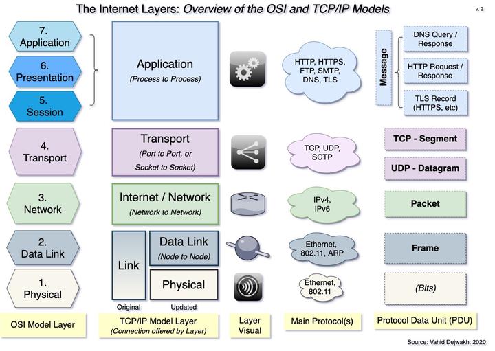
Before we start digging deeper into the layers of the Internet, we should briefly discuss the fact that there are two main models:
- the Open Systems Interconnection (OSI) Model, and
- the TCP/IP Model.
The OSI model is a conceptual, theoretical model developed in the 1980s by an international group of engineers and scientists working under the auspices of the International Organization for Standardization (ISO).
The model standardized a layered approach to telecommunications, where each layer provides a certain level of abstraction and functionality. Each layer also contains some encapsulated data to be opened and used by the layer directly above it.
The OSI Model identified seven layers, numbering them from lowest to highest: 1) Physical, 2) Data Link, 3) Network, 4) Transport, 5) Session, 6) Presentation, and 7) Application.
The older, TCP/IP model was originally funded and developed by the US Department of Defense (DoD) in the 1970s, and is also known as the Internet protocol suite.
This practical model focused on establishing protocols for communication, the main ones being the Internet Protocol (IP) and the Transmission Control Protocol (TCP), after which the model was later named.
Although the original TCP/IP document did loosely define a four-layered model, it did not number them, and actually emphasized architectural principles more than layering.
Some architectural principles included encapsulation, and the robustness principle, which states that an implementation must be conservative (i.e. strict) in its sending behavior, and liberal (i.e. flexible) in its receiving behavior.
The original four layers were named Application, Transport, Internet, and Link.
For many reasons, perhaps partly because of its less prescriptive approach, TCP/IP took off and remains the dominant model still in use today.
For the rest of the series on How the Internet Works, we will only use the TCP/IP model, albeit an updated, five-layered version that breaks down the Link layer into the first two layers of the OSI model–namely, Physical and Data Link. This updated version also renamed the third layer from “Internet” to “Network” to match the OSI model, but I actually prefer the original term so we’ll stick with that.
In the next sections, we’ll look at what each layer does, starting from the Physical layer all the way up to the Application layer.
Finally, we’ll take a look at an example of what happens at each layer when you enter a URL in your browser. This example will help solidify how the layers work together.
1. Physical Layer

The Physical layer is the most rudimentary and foundational level, on top of which all the other layers rest.
This layer concerns itself with transmitting signals, or bits, either over a coaxial or fiberoptic wire or a wireless medium, like Wi-Fi.
2. Data Link Layer

The second layer is the Data Link layer, which interprets the physical transmissions of Layer 1, and converts them into a Frame.
A Frame is a piece of data, or more specifically a protocol data unit (PDU), that contains a source MAC Address, a destination MAC Address, and some encapsulated data to be read later by Layer 3.
LANs, NIC Cards, and Switches all function at this layer. Switches read and process each frame, and send them to the appropriate device on the network that has the frame’s destination MAC Address.
Because this layer delivers data from one point (or node) on a network to another, it is referred to as providing a node to node connection.
The important protocols at work here are the Ethernet (wired) and the 802.11 (Wi-Fi) protocols. The Address Resolution Protocol (ARP) is what a switch, or a router operating at Layer 2, uses to convert an IP Address to a MAC Address when creating a frame.
3. Internet Layer
The Internet layer is where the majority of the action takes place, because that’s where the data travels across routers, from network to network.
The main protocols at work here are the Internet Protocol version 4 (IPv4) and the Internet Protocol version 6 (IPv6).
At this level, routers open up the frame, and read the encapsulated data, which is known as a Packet.
A Packet is an Internet-layer PDU that contains a source and destination IP Address, and some encapsulated data to be read later by Layer 4.
Routers then progressively forward the packet to the router that will get it closer to its destination, until it finally arrives to the destination network containing the destination IP address.
For this reason, the Internet layer is known as providing a network to network connection.
There is some more complexity that happens at this layer, which we’ll get to later when we discuss an example of what happens in an HTTP request/response cycle. For now, this level of detail should be sufficient.
4. Transport Layer
 The Transport Layer is the first layer that takes place on the actual host device, whether that’s the client or the server.
This layer opens the encapsulated data from layer 3, which is either a segment or a datagram, depending on the protocol used.
A Segment is a Transport-layer PDU that operates with the TCP protocol, which is a connection-oriented protocol that ensures reliability. Any form of communication that requires reliability and integrity, like processing credit card payments, loading web pages, or transferring files, is done through TCP segments.
In Part III, we’ll take a closer look at how TCP Segments provide reliability.
A Datagram is a Transport-layer PDU that operates with the User Datagram Protocol (UDP), which is a connection-less protocol that favors speed. Any form of communication that requires receiving continuous updates or streams of data with no need to worry about the occasional dropped bits, such as videoconferencing (e.g. Zoom) or voice-over-ip (VOIP) is accomplished through UDP datagrams. DNS queries are also usually done through UDP because of its faster speed.
Both Segments and Datagrams contain source and destination ports, as well as an encapsulated payload to be read by Layer 5.
A port is a specific channel on a device. Each tab you open on a browser opens on a new port on your computer. Each application type typically runs on specific port ranges.
On the server side, for example, web pages are served from port 80 (or 8080), and DNS responses go out from port 53. Mail servers now typically run on port 587, which is dedicated for secure Simple Mail Transfer Protocol (SMTP).
The combination of an IP address and a port number makes up a unique Socket.
That’s why the Transport layer is known as providing a port to port connection, or a socket to socket connection–which essentially mean the same thing.
The process of sending the contents of received datagrams and segments to the correct destination ports is known as demultiplexing. The reverse process, which is gathering content from all the ports, and blending them into a single channel is known as multiplexing.
When dealing with TCP, segmentation and reassembly also occur at this layer. We’ll discuss this process later in this article.
5. Application Layer
Finally, once the content of segments or datagrams is sent to the correct port, the Application layer is finally ready to read the encapsulated data, which is a Message (sometimes also simply called Data).
A Message is an Application-layer PDU that can contain many different things, depending on what Application process runs on that port, and/or what protocol was used to encapsulate the message in the first place.
A Message can be, among other things, an HTTP request, an HTTP response, a DNS query, a DNS response, an SMTP message, or a TLS record (used for HTTPS). We’ll go deeper into TLS and HTTPS in Part III, but they are essentially an additional layer of security.
Each Application process runs on a dedicated port. That’s why this layer is known as providing a process to process connection.
How do all these layers work together? What happens when you enter a URL in your browser? That’s what we’ll address next.
6. Layered Trip Through an HTTP Request/Response Cycle
To better understand and appreciate how all the five layers work together, it’s helpful to break down all the steps that happen from the time we enter a URL in our browser to the time we get a page loaded.
Although we were conceptually introduced to the basics of each layer from the Physical layer up, in reality the HTTP request/response cycle (and any communication) actually goes from the Application layer down, and then back up again.
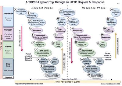
There’s a lot going on here–30 steps to be more precise. Let’s take a look at each one, in order.
-
Request Phase - Client Side
- User enters a URL in browser tab - Let’s say we entered google.com
- DNS Lookup to get destination IP - If our browser had never been to this site before, it would have to first send a DNS query in order to find the destination IP address of the google.com domain. That would of course require a separate DNS query/response cycle. Here, we are assuming we’ve been to the site before and therefore have the IP address saved in our browser’s cache.
- HTTP Request sent to Port 7124 of User’s device - Your port number might be different, of course. Each opened browser tab you have uses a unique port.
- Multiplexing - The client processes signals from all ports, including the one sent to 7124, and prepares them for transmission over a single channel.
- Segmentation divides HTTP Request into Segments - This breaks up the HTTP Request message into multiple pieces, each to be contained in a separate segment. Henceforth we’ll just focus on the journey of one segment, but the same is happening for all the other segments of our HTTP Request.
- Segment is wrapped in a Packet
- Packet travels across Internet routers - This is a simplification of what is actually a little more complicated than the diagram shows.
In reality, the packet keeps being wrapped in a new frame (i.e. Layer 2) so it can travel to the next hop, then opened again as a packet (back to Layer 3), and wrapped again in a new frame with an updated destination MAC address, etc.
After many hops, however, it finally arrives at the destination network, which in this case is the network that the server with the destination IP address is on.
-
Request Phase - Server Side
- Packet is wrapped in a Frame - This is the final frame on this leg of the trip, containing the server’s MAC address as the destination MAC address.
- Frame travels across network to the destination server
- Server receives frame through its NIC card - Note that this step also involves Layer 1, since the NIC Card is interpreting the signals it receives, either via a cable or wirelessly. The same could be said about the Routers on Layer 3, since they also have to process physical signals.
- Server opens frame
- Server opens packet
- Reassembly - Server receives all the segments and reassembles them into the HTTP Request.
- Demultiplexing - This process sends each compiled message to the appropriate port–which is 80 in the case of a server processing an HTTP request.
- Server opens Request on Port 80
-
Response Phase - Server Side
- Server processes Request and generates a Response - Occasionally, a server may need to generate multiple responses. An HTTP response will include a status code indicating whether the server found the information or not. More on this in Part III.
- Server sends Response to Port 80
- Multiplexing The server processes signals from all ports, including the one sent to 80, and prepares them for transmission over a single channel.
- Segmentation - The response is divided up and wrapped in separate segments. We’ll focus on one segment for the rest of this leg, but the same thing is happening to all segments.
- Segment is wrapped in a Packet
- Packet travels across Internet routers - Same comment applies here as the one in Step 7 above.
Packet arrives at the destination network, i.e. the client’s network.
-
Response Phase - Client Side
- Packet is wrapped in a Frame - This is the final frame for this leg of the trip, containing our client’s MAC address as the destination MAC address.
- Frame travels across network to the destination client - For most people working from home, this would be the home LAN, but it could also be the coffee shop’s WLAN or the office intranet.
- Client receives frame through its NIC card - Same comment here as step 10.
- Client opens frame
- Client opens packet
- Reassembly - Client assembles all the segments back together to recreate the HTTP response
- Demultiplexing - The response is sent to the appropriate port, which is 7124 in the case of our specific tab that sent the original request.
- Client opens Response on Port 7124 - This may involve the browser interpreting the HTML page, applying CSS, and running the Javascript.
- Client’s browser tab displays the requested URL page - We enjoy our page.
Wow, what a long trip!
This entire process constitutes one round-trip time (RTT), which is the time it takes for data to go all the way to a server and then come back to the client.
It’s amazing to think that this RTT typically happens within a fraction of a second.
Now that we’ve gotten a taste of the various layers involved in the Internet, and the PDU of each layer, we are ready to dig even deeper.
In Part III, we’ll get into more detail of what each PDU contains. In the process, we’ll also understand how security works. We’ll review what happens in a TCP handshake and why TCP provides a more reliable connection than UDP, but at the cost of time.
We’ll also see what TLS is, and how certificate authorities authenticate a site.
Vahid Dejwakh
Software Engineer at Microsoft;
Lover of good music and poetry
Vahid writes about interesting ideas at the intersection of software, system design, data, philosophy, psychology, policy, and business. He enjoys coffee and has a palate for spicy and diverse foods.