How the Internet Works, Part III - Reliability and Security
How the Internet Layers Contribute to Reliability and Security
In Part II, we learned how an HTTP request travels across the Internet to the correct destination server, through several layers, and returns with a response. But how does this happen reliably and securely, without becoming corrupted or being intercepted by a malicious hacker? And what’s HTTPS?
To be able to answer these questions, we need to first dig deeper into what each layer’s protocol data unit (PDU) contains. In this process, we’ll appreciate how each layer contributes to reliability. Then we’ll be able to discuss what TLS and HTTPS are, and how they contribute to secure transmissions.
That’s what we’ll do here, which is Part III of the three-part series on How the Internet Works.
If you haven’t read Part II, please go read that first. Everything here builds on the layers covered in Part II.
III. Reliability and Security
- Intro. Layered Reliability and Security
- 1. Physical Layer bits
- 2. Data Link Layer PDU - Frames
- 3. Internet Layer PDU - Packets
- 4. Transport Layer PDU - Datagrams and Segments
- 5. Application Layer PDU - Messages
- 6. TLS and HTTPS
- PDF of the Internet Layers - In-depth Breakdown
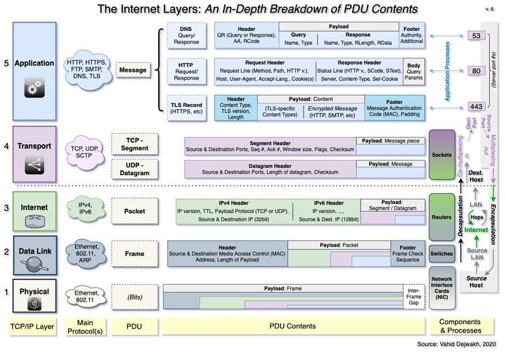
Introduction - Layered Reliability and Security
The concept of encapsulating each layer’s PDU provides a basic foundation for how various Internet security measures function. Most fundamentally, encapsulation is a way to enclose certain bits of data to render them inaccessible from external contexts.
We’ve already explored how each layer encapsulates data further as you go down the layers, from the Application layer downward. For example, Message data cannot be opened by the Transport layer, and Segment data cannot be opened by the Internet layer, etc.
Each layer therefore secures its contents from the layer beneath it.
In the next sections, we’ll take a look at each layer’s PDU, starting with the physical layer and up.
We’ll explore what each PDU contains, and how both the layer and the PDU’s contents contribute to establishing a reliable and secure signal transmission.
1. Physical Layer bits

As discussed in Part II, the Physical layer allows the entire system to function. Consisting of bits transmitted either across a wire or wirelessly, the physical layer contains a payload that will be progressively decoded by higher layers.
Although the Physical layer doesn’t technically contain anything that can be classified as data yet, and therefore does not have a PDU, there is nevertheless a concept worth addressing–the Interframe Gap.
The Interframe Gap (IFG) is a required pause in the signal transmission, which lets a NIC card operating on layer 2 know that a frame was completed and another may begin. The IFG is noteworthy because of its absence of data.
The physical layer’s IFG therefore contributes to reliability by ensuring that the signals of one frame don’t get accidentally mixed up with the signals of another frame during the initial transmission.
2. Data Link Layer PDU - Frames

The Data Link layer converts the physical transmissions of Layer 1 into a Frame, which is the first formal PDU.
In addition to containing the source and destination MAC addresses of where this frame originated from and is going to, a frame contains an encapsulated payload, and a Frame Check Sequence at the end.
This Frame Check Sequence (FCS) is what the Data Link layer uses for error detection, to make sure that the frame has neither lost any bits along the way, nor has been corrupted due to signal interference.
The sender of the frame uses an algorithm that computes a number based on the frame’s data, and tags this computed number at the end (i.e. footer) of the frame. Whenever a receiving NIC card reads the frame, it also uses the same algorithm to compute a number based on the received bits.
If this computed number is not the same as the FCS number on the footer, the device considers the frame corrupted and discards it.
The FCS therefore provides an error detection process, using what is commonly and more generally known as a checksum (i.e. comparing or checking an algorithm-computed number against a received number or sum).
As we’ll see in subsequent sections, other PDUs also use some form of checksum.
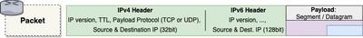
3. Internet Layer PDU - Packets
The Internet Protocols used in layer 3 truly comprise the cornerstone of the Internet protocol suite that make the modern Internet possible.
MAC addresses v.s. IP Addresses
If we did not have IP addresses and had to rely simply on MAC addresses to connect a client and a server, the process would be profoundly inefficient and time consuming, because every device would need to somehow keep track of where all the most-used destination servers are, and the MAC addresses of all the routers along the way–and we’d need to keep updating these routes every single time a router or server is replaced, since each device has a unique MAC address.
This would create such a hassle and nightmare that the Internet would surely not have evolved as smoothly and fast as it has.
Thanks to the logical and dynamic nature of IP addresses, however, that’s not a concern.
IPv4 v.s. IPv6 (“Oh, we’ll never run out of 4.3 billion addresses!")
The main difference between packets encoded in IPv4 and those encoded in IPv6 is the size of the space reserved on the packet’s header for the source and destination IP addresses.
In IPv4, 32 bits were reserved, which meant that there could be up to 2^32, or about 4.3 billion unique combinations (i.e. 4.3 billion IP addresses). This was fine in the 1990s and even early 2000s when there weren’t that many devices connected to the Internet.
Now, however, we have either reached or are close to reaching this number, and many companies have started deploying IPv6-capable routers.
As of December 9, 2020, according to the WorldIPv6Launch group, about 74% of Comcast’s routers and 84% of Verizon’s routers were IPv6 capable.
IPv6 reserves 128 bits for the source and destination IP address fields. This should be able to accommodate 2^128 addresses, which is equal to 340 trillion trillion trillion IP addresses.
Time To Live
Lastly, it’s worth talking about the Time-To-Live (TTL) field that is on a packet’s header. The purpose of this number is to make sure that packets don’t get somehow caught in limbo or otherwise run around continuously across routers, never finding their destination yet taking up bandwidth unnecessarily.
They may originally start out with, for example, a TTL of 64. At every hop, the router decrements that number by one. Once the TTL reaches 0, the packet is discarded and not allowed to be forwarded along anymore.
This hop limit helps to ensure that packets traveling on Internet routers don’t live forever, which helps to reduce congestion and thereby improve the performance and reliability of existing networks.
Who wants to live forever anyway?
4. Transport Layer PDU - Datagrams and Segments
![]()
Datagrams
Let’s quickly address UDP Datagrams first, so we can actually spend the majority of this section discussing the TCP handshake and the (many) other reliability features of TCP segments.
The main reliability feature of Datagrams is the checksum, which datagrams actually have in common with segments. As mentioned previously, a checksum is an error detecting mechanism ensuring the PDU received contains the same content as the PDU sent.
Segments
The TCP protocol’s primary advantage compared against UDP is its reliability.
When we said in Part II that TCP was a connection-oriented protocol, what we meant was that before any data can even be exchanged, the TCP protocol requires that a connection first be established between the client and the server.
1) TCP Handshake and Flags
The TCP Handshake establishes this initial connection, using the Flags component of the segment header. The TCP handshake is also sometimes called a three-way handshake, because it uses a three-step process that takes one and a half RTTs (round-trip times).
This process goes as follows:
- The client sends an empty (i.e. with no payload, or bodyless) SYN segment (i.e. where the segment header’s SYN flag is set to true, or on)
- The server receives the segment and replies with another bodyless segment with the SYN and ACK flags turned on
- The client receives the server’s segment and sends a final acknowledgment back to the server, which is a bodyless segment containing only the ACK flag turned on.
Immediately after that’s complete, the client begins sending the actual HTTP request (or whatever is being sent in the Message).
2) Segmentation and In-Order Delivery
We briefly saw in Part II how TCP enables segmentation, which is the breaking up of the Message into multiple segments so that these can travel in separate packets. The advantage of this, aside from merely being able to handle large data transfers that can’t fit in a UDP datagram, is that it also enables in-order delivery.
With datagrams, there’s no concept of order. The datagram is simply processed in order that it is received, regardless of whether datagram 10 actually arrives before datagram 8, for whatever reason.
With segments, however, sequence is preserved using the Sequence # field in the header. This field is filled in during the segmentation process. As soon as a segment is received, a parallel, bodyless reply is sent with the corresponding Acknowledgment # filled in (note: not to be confused with the ACK flag used in the handshake, which is a boolean on/off switch).
That is to say, as soon as the segment with Sequence #10 is received, the receiving host immediately replies with an empty segment with acknowledgment #10 on the header, which indicates to the sender that segment #10 was properly received.
As you probably guessed, this sequence number is also how the Message is reconstructed in-order during the Reassembly phase.
Speaking of reassembly, how does the receiver know the package is complete and there are no more segments still on the way?
When the sender has received all acknowledgments back and there are no more segments left to send, the sender will send an empty segment with a FIN flag turned on. The receiver replies with a segment containing the FIN and ACK flags, indicating the reception of the finished segment. Finally, the sender replies with an ACK segment indicating the end of the transmission. This parallels the initial handshake, but uses the “FIN” flag instead of “SYN”.
3) Pipelining and Window Size
It would take a very long time to send a message if the sender had to send each segment one at a time, waiting to receive the acknowledgment back before moving on to the next segment.
Thankfully, that’s not what happens.
Pipelining is the concept of sending multiple signals at the same time, to maximize bandwidth use. The analogy, for those who’ve ever moved before, is dividing up and sending your belongings into multiple trucks (or cars) instead of having to wait for the one truck to go back and forth several trips.
Exactly how many “trucks” are working simultaneously is determined by the Window size on the segment header. For example, a size of 5 means that 5 segments are sent at a time. That means that the sender doesn’t move on to the next 5 segments until it has received an acknowledgment from the receiver for those 5 segments (i.e. our 5 trucks have returned).
If sufficient time has passed and the sender has still not received an acknowledgment back on any segment, the sender actually resends that segment (retransmission of lost data). This ensures no segment is dropped.
Any segment already received (i.e. with the same Sequence # as an already-received segment) is simply dropped (known as de-duplication).
4) Flow Control
The sender is not the only one that takes advantage of the Window size field, however.
With every acknowledgment that it sends back, the receiver uses the Window Size to indicate how many segments at a time it is currently capable of receiving. This helps the sender determine how busy the receiver is, and thereby adjust its sending window size accordingly. That’s how TCP provides Flow Control.
5) Congestion Avoidance
Another related concept is congestion avoidance, which is slightly more complicated. Although flow control helps the sender determine how busy the receiver is, it doesn’t really say anything about how busy the traffic is.
Using an algorithm that keeps track of how long it takes to receive acknowledgments back, the sender gets a sense of how congested the network is, and adjusts its sending behavior accordingly. This helps to reduce network congestion, and ensures transmission is only occurring when there’s some bandwidth capacity.
Summary
To recap and conclude, here’s a useful table that summarizes the main features of TCP segments, and which reliability concept each one achieves.
| Reliability Concept | TCP Feature |
|---|---|
| 1. Establishing & Closing Connection | TCP Handshake, Flags |
| 2. Segmentation | Seq # |
| 3. In-Order delivery | Seq # |
| 4. Error detection / Data integrity | Checksum |
| 5. Retransmission of lost data | Ack # |
| 6. De-duplication | Seq # |
| 7. Pipelining | Window size (sender) |
| 8. Flow control | Window size (receiver) |
| 9. Congestion avoidance | Ack #, algo |
5. Application Layer PDU - Messages
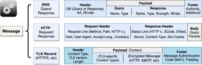
As we discussed previously, there are many different types of messages at the Application layer–the three in the diagram above are only some examples.
DNS Query / Response
Every communication on the Internet requires a destination IP address, which means everything starts with a DNS query–which is how a browser (or other web application) discovers the IP address of a particular domain name.
Although the DNS Query/Response actually contains more than we will discuss here, these are the main relevant pieces.
The Header includes two booleans: 1) a QR flag turned off for a Query and on for a Response, and 2) a AA turned on if the response is an Authoritative Answer (off if it’s a query or non-authoritative). The header also includes a Response Code, indicating the status of the response.
An answer is considered authoritative only if it’s coming directly from the originating DNS server itself, and not an intermediary DNS server (e.g. an ISP or other secondary DNS server that has cached a previous answer from the authoritative source).
The payload contains the actual domain Name being queried and the query record type. The most common record Types include:
- A - a hostname that uses IPv4,
- AAAA - a hostname that uses IPv6,
- CNAME - a canonical name record, or a hostname alias,
- MX - Mail exchanger record, and
- NS - name server record.
The payload of a response also contains the Length of the response, and the Response Data itself (e.g. the IP address, or multiple IP addresses).
Finally, the DNS message also includes a footer that contains some additional information, including some authority-related information.
Because a DNS Query/Response is small in size and speed is a priority, they are typically carried via UDP. The UDP’s checksum provides a sufficient error detection process.
HTTP Request
The HTTP Request message contains a Header, which can be further divided into two sub-components: 1) a Request line, and 2) a set of Headers. The request line contains the most important components and is required, but headers are optional.
The three items in the Request Line are separated by a space.
An empty line separates and delineates the Header from the Body.
The Body of a request is typically empty, but would contain the query parameters of a POST request (if there are any).
| PDU Section | Sub-Component | Content |
|---|---|---|
| Header | Request Line | HTTP Method | Path (the full URL for GET) | HTTP Version |
| Headers | Key-value pairs, e.g. Host, User-Agent, Accept-Language, Cookie(s), etc | |
| Body | Empty except for POST request Query Parameters |
Several important HTTP Methods include: GET, POST, PUT/PATCH, and DELETE. These characterize the type of interaction the client seeks from the server, with the GET request being the most basic, read-only type of request.
Any query parameters used in a GET request are included in the Path of the Request Line. For POST requests, however, query parameters are separated out and part of the Body.
HTTP Response
The HTTP Response message contains a Header, which can be further divided into two sub-components: 1) a Status line, and 2) a set of Headers. The Status line contains the most important components and is required, but headers are optional.
The three items in the Status Line are separated by a space.
An empty line separates and delineates the Header from the Body.
The Body of a response contains the actual contents returned by the server, e.g. the HTML page.
| PDU Section | Sub-Component | Content |
|---|---|---|
| Header | Status Line | HTTP Version | Status Code | Status Text |
| Headers | Key-value pairs, e.g. Server, Content-Type, Set-cookie, etc | |
| Body | Actual contents from the server, e.g. HTML page, etc |
Both HTTP Requests and Responses happen over TCP, which allows the message to be broken up into segments, and provides additional reliability.
TLS Record
The last type of message we’ll mention is a TLS Record, which actually functions more like another layer of encapsulation than the other two more “regular” message types we just discussed.
A TLS Record payload contains either some TLS-specific content, or the encrypted piece of the Application-layer Message we are sending (e.g. HTTP request/response).
Let’s discuss TLS (and TLS record contents) in more detail in the next, final section.
6. TLS and HTTPS
Although TLS stands for Transport Layer Security, it is currently technically part of the TCP/IP’s Application layer, and provides encryption to any other Application-layer message type.
TLS is mainly used to encrypt HTTP messages, thereby creating Secure HTTP, or HTTPS (aka. HTTP/TLS, or “HTTP over TLS”).
It might be helpful to conceptually think of TLS as being an imaginary Security Layer in between the Transport Layer and the Application Layer. My mother always told me that if I wished for something hard enough, one day it might come true. So, you know, who knows?
TLS dates its origins back to the Secure Sockets Layer (SSL) technology developed by Netscape. Can I get a clap for Netscape Communicator?
Although TLS only works on top of TCP, there is another protocol called DTLS which is the equivalent of TLS, but for UDP. We won’t talk about DTLS here.
TLS Record
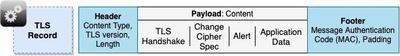
In the first stages of the TLS process, which happens immediately after the TCP handshake is completed, the TLS handshake takes place.
After that’s successfully completed, every subsequent record contains the encrypted application message, which might be an HTTP request or response.
Before we get into the details of each content type, let’s look at the Message Authentication Code (MAC), which is on the record’s footer. This is essentially a form of a checksum, but instead of serving as a check against corruption, it serves as a check against data tampering. It uses the same symmetric key exchanged in the TLS Handshake to generate the MAC, thereby ensuring that the contents came from the same source.
We’ll understand better how it does this when we talk about the Cipher suite and the encryption keys exchanged during the TLS Handshake. Some common cipher suites, or encryption algorithms, include RSA and Diffie-Hellman (DH).
1) TLS Handshake & ChangeCipherSpec
Right after the client sends the third part of the TCP handshake, i.e. the “ACK” segment, the client also initiates the first part of the TLS handshake, which is the ClientHello step.
Let’s take a look at each step of the process using this table.
| TLS Handshake Step | Actor | Record Sent | Content Type | Description |
|---|---|---|---|---|
| 1 | Client | ClientHello | TLS Handshake | The client sends the list of ciphers and the highest TLS version it is capable of supporting |
| 2 | Server | ServerHello | TLS Handshake | The server responds with the cipher and TLS version that it has decided they should use |
| Certificate | TLS Handshake | The server sends its certificate, which includes its public key | ||
| ServerDone | TLS Handshake | The server indicates it is done with Step 2 | ||
| 3 | Client | ClientKeyExchange | TLS Handshake | The client uses the server’s public key to encrypt and send a pre-master secret key, which they will both use to generate the same symmetric key |
| ChangeCipherSpec | ChangeCipherSpec | This second record lets the server know that encrypted communication should now begin with the use of the symmetric key | ||
| Finished | TLS Handshake | The client indicates it is done with the TLS Handshake | ||
| 4 | Server | ChangeCipherSpec | ChangeCipherSpec | The server uses its private key to decrypt the pre-master secret key, which it then uses to create the symmetric key. It lets the client know it has started using the symmetric key too |
| Finished | TLS Handshake | Finally, the server indicates it is also done with the TLS Handshake process |
2) Alert
At any point of the TLS Handshake, if any error or problem occurs, the client or server will send a record with the Alert content type. This could be, for example, because the client doesn’t support the minimum level of TLS version required by the server, which would signal a failed TLS handshake process. Another Alert might be because of a problem related to the Certificate.
3) Application Data
After the TLS Handshake is successfully completed, all the subsequent messages sent and received are TLS records containing the encrypted piece of the HTTP request or HTTP response.
The headers of these records would be marked with the Application Data content type. The receiver would need to decode them back to the original HTTP request or response before being able to process or display the contents.
Certificate Authorities
Each site’s certificate (which the server sends in step 2 of the TLS handshake) is signed by an Intermediate Certificate Authority (CA) that certifies the certificate’s authenticity. Each CA in turn derives its authority from another intermediate CA higher up the chain, all the way up to the Root CA.
The hierarchical structure of certificate authorities establishes the Chain of Trust from the original site all the way to the Root CA.
Vahid Dejwakh
Software Engineer at Microsoft;
Lover of good music and poetry
Vahid writes about interesting ideas at the intersection of software, system design, data, philosophy, psychology, policy, and business. He enjoys coffee and has a palate for spicy and diverse foods.